Introduction
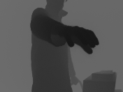
Early this year we received the 3D Camera O3D303 from IFM. The camera captures 3D images with the size of 176×132 from a distance up to 8m. The user can retrieve the 3D images from the camera via TCP/IP. IFM published the protocols to access the images from the camera on their download site. Picture 1 is a 3D image showing a person stretching out his hand. The brightness of the image pixels indicates the distance of each pixel from the camera lens.
We have talked this year to a company, which is selling driverless transport systems. We thought we can help them to apply our camera to a specific problem they have with their driverless transport systems. Unfortunately their interest was limited, but they were interested in another use case related to this topic. This company is trying to cut costs of their products by looking for a substitute for their 3D camera. The idea was to train a neural network on a constrained environment with images from regular cameras and from a 3D camera. During the normal operation the driverless transport system should then capture images with regular cameras and predict 3D images with a trained neural network. We have not made any business case with this company, however we kept the idea and continued to do research on it.
Experimental setup
The first goal was to build an experimental setup, which enabled us to capture regular color images and 3D images needed to train a neural network. Later we use the same setup for our testing to predict 3D images. We have built a frame with bar profiles and a top-hat rail to attach power supplies (5V and 24V) and a Jetson Nano computer, see Picture 2 top and below. It is the first time we used a Jetson Nano computer and were looking forward learning about its performance.
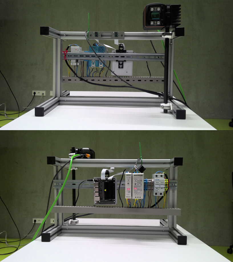
On the upper picture you see on the top bar profile two camera serial interface (CSI) cameras attached with 8cm distance to each other. This is roughly the humans eyes distance which we want to duplicate. The Jetson Nano (on the top-hat rail, picture below) has two CSI interfaces, so we connected the cameras to it.
The IFM camera was attached on the frame on the top, see top picture upper right corner. It requires 24V from the power supply. To capture images with the Jetson Nano, we use the 3D camera’s ethernet interface.
Below some globally defined variables, which show up frequently in this article. The dimension of all images we use are 128×128. We also defined a path for the image data (path). Image data for training, validation and testing are stored in the “left”, “right” and “3d” directories (dataleft, dataright, data3d).
dim = (128, 128)
limit = 128

path =  r'...\3D'

dataleft = os.path.join(path, r"data\left")
dataright = os.path.join(path, r"data\right")
data3d = os.path.join(path, r"data\3d")
The producer process to trigger image capturing
The Jetson Nano has two CSI interfaces for both CSI cameras. Unfortunately the Jetson Nano’s hardware is not synchronizing both cameras. You can see this problem, when a program displays the captured images in real time with OpenCV. The program will show a delay while displaying both images. It becomes even worse, when the program displays 3D images in real time from the 3D camera.
Another goal is to create a large number of training, validation and testing images from the left, right and 3D camera. However the delay between the captured images complicates the image collection, because the scenes to be captured need to be frozen.
We figured out, that if we run programs to capture images in three separate processes, the ubuntu operating system, which is installed on the Jetson Nano, is doing synchronization. Delays between the left and right camera cannot be seen in such an extent anymore. Only the 3D camera shows a little delay. We assume this is due to the reaction time of the 3D camera itself. So before wiring extra hardware, we decided to to let the operating system do the synchronization job.
So the decision was made to have three separate processes to capture images from all the three cameras. In order to do this, we implemented a cross process communication, so a producer process can trigger commands to three consumer processes, which capture images from the left, right and 3D cameras. For simplicity we use memory mapping and a file named command.txt with size 140 bytes. The code below shows how this file is created, so all three image capturing processes can consume its content in form of a json string.
COMMANDSIZE = 140
COMMANDNAME = "command.txt"
text = '{"count" :0, "command": "none", "attr": ""}'
text = text.ljust(COMMANDSIZE)

textfile = open(COMMANDNAME, "w")
textfile.write(text)
textfile.close()
The producer program calls the function setdata, which takes a number (counter), a command string (command) and an attribute string (attr) as parameters and writes the content into a json string, see below. The json string is moved into a memory map, which is linked to the command.txt file.
def senddata(counter, command, attr):

    with open(COMMANDNAME, "r+b") as f:
        data = {"count": counter, "command": command, "attr": attr}
        datastr = json.dumps(data)

        datastr = datastr.ljust(COMMANDSIZE)

        mm = mmap.mmap(f.fileno(), 0)

        print(datastr.encode('utf-8'))
        mm.write(datastr.encode('utf-8'))
Below an example how the producer program triggers the image capturing on all three consumer processes. It sends additionally a string with time and data information. The consumer processes use this string to create names for their captured images.
now = datetime.now()
date_time = now.strftime("%m_%d_%Y__%H_%M_%S")
senddata(count, "shoot", date_time)
count += 1
The function senddata above takes count, “shoot” and date_time and writes them into the command.txt file. The consumer processes (the running left, right and 3D camera image capturing programs) are constantly reading this file, while the variable count is used to sense if a new command is issued.
Consumer’s processes to capture images
We implemented three separate image capturing programs (consumer processes) and run them as different processes. The producer process sends out commands via memory map, which is linked to the command.txt file. All three consumer processes are repeatedly reading the command.txt file to find out if a new command was issued. This is done by checking for an increased count value.
Below you see the function getdata, which reads the json string out of command.txt, parses the json content and returns the values from it.
COMMANDSIZE = 140
COMMANDNAME = "command.txt"

def getdata():
    with open(COMMANDNAME, "r+b") as f:
        mm = mmap.mmap(f.fileno(), 0)
        strdata = mm.readline().decode('ascii')

        data = json.loads(strdata)

        return data["count"], data["command"], data["attr"]
Image capturing with the 3D camera
The documentation of IFM’s O3D303 camera can be found here. Prior to accessing the camera via TCP/IP, we have configured the camera to use dhcp, so the 3D camera can retrieve an IP address. The Jetson Nano gets the 3D camera’s IP address with the help of the linux nmap command, which scans all IP addresses in its network environment. The nmap command returns all MAC addresses related to the IP addresses. Since we know the MAC address of the camera, we can parse out the IP address from nmap‘s output. See code below.
os.system('nmap -sP 143.90.26.0/24')
lines=[]
out = os.popen('arp -a').read()
lines = out.splitlines()

matching = [s for s in lines if "00:02:21:41:ef:53" in s]
matchstr = matching[0]
ip = matchstr[matchstr.find("(")+1:matchstr.find(")")]
Communication between IFM’s 3D camera and the Jetson Nano is done via TCP/IP sockets. We have written the class Frame to retrieve 3D images from the 3D camera, see code below. The 3D camera opens per default port 50010 and sends out frequently 3D image data. Our 3D image capturing program, which is using the class Frame, connects to the 3D camera with the socket’s connect method. As a parameter the program needs to pass the 3D camera’s IP address and the port number (which is 50010). The method trigger of class Frame catches the image data, which is sent by the 3D camera. It parses the data stream, until is finds the string “\r\n0000start”. The remaining 255830 bytes of data contains data of a single scene in five different image representations which are subsequently stored in Frame‘s attributes img0, img1, img2, img3, img4. See also chunktypes for names of the image representations. Note that the number 255830 depends on the 3D camera configuration, which can be set with an additional O3D303 software. We however use the factory settings, so we did not change the configuration. The receiveAll method receives the 255830 bytes and stores the data into the variable frame.
Each image representation consists of a header with header size, image type, width, height, and pixel format and a body with the image raw data. Inside the method trigger, the program reads the images from the variable frame using the header’s width, height and pixel format information and stores them into the Frame‘s img0, img1, img2, img3, img4 attributes.
class Frame:

    def __init__(self):
        self.chunktypes = {
            100: "RADIAL_DISTANCE_IMAGE",
            101: "NORM_AMPLITUDE_IMAGE",
            103: "AMPLITUDE_IMAGE",
            104: "GRAYSCALE_IMAGE",
            200: "CARTESIAN_X_COMPONENT",
            201: "CARTESIAN_Y_COMPONENT",
            202: "CARTESIAN_Z_COMPONENT",
            203: "CARTESIAN_ALL",
            223: "UNIT_VECTOR_ALL",
            300: "CONFIDENCE_IMAGE",
            302: "DIAGNOSTIC",
            305: "JSON_DIAGNOSTIC",
        }

        self.pixelformat = {
            0: "FORMAT_8U",
            1: "FORMAT_8S",
            2: "FORMAT_16U",
            3: "FORMAT_16S",
            4: "FORMAT_32U",
            5: "FORMAT_32S",
            6: "FORMAT_32F",
            7: "FORMAT_64U",
            8: "FORMAT_64F",
            9: "Reserved",
            10: "FORMAT_32F_3",
        }

        self.pixelsize = {
            0: 1,
            1: 1,
            2: 2,
            3: 2,
            4: 4,
            5: 4,
            6: 4,
            7: 8,
            8: 8,
            9: 0,
            10: 0,
        }

    def getChunkType(self, data):
        return int.from_bytes(data[0:4],"little")

    def getChunkSize(self, data):
        return int.from_bytes(data[4:8],"little")

    def getHeaderSize(self, data):
        return int.from_bytes(data[8:12],"little")

    def getHeaderVersion(self, data):
        return int.from_bytes(data[12:16],"little")

    def getImageWidth(self, data):
        return int.from_bytes(data[16:20],"little")

    def getImageHeight(self, data):
        return int.from_bytes(data[20:24],"little")

    def getPixelFormat(self, data):
        return int.from_bytes(data[24:28],"little")

    def getTimeStamp(self, data):
        return int.from_bytes(data[28:32],"little")

    def getFrameCount(self, data):
        return int.from_bytes(data[32:36],"little")

    def connect(self, ip, port):
        self.s = socket.socket(socket.AF_INET, socket.SOCK_STREAM)
        self.ip = ip
        self.port = port
        self.s.connect((self.ip, self.port))

    def close(self):
        self.s.close()

    def receiveAll(self, num):
        chunks = []
        bytes_recd = 0
        while bytes_recd < num:
            chunk = self.s.recv(min(num - bytes_recd, 2048))
            if chunk == b'':
                raise RuntimeError("socket connection broken")
            chunks.append(chunk)
            bytes_recd = bytes_recd + len(chunk)
        return b''.join(chunks)

    def trigger(self):

        replies=[]
        reply=0
        frame = b''
        while reply!=b'\r':
            reply = self.s.recv(1)
        reply = self.s.recv(1)
        assert(reply==b'\n')
        reply = self.s.recv(4)
        assert(reply==b'0000')
        reply = self.s.recv(4)
        assert(reply==b'star')

        frame = self.receiveAll(255830)
        assert(frame[255824:255830]==b'stop\r\n')

        posimage0 = 0
        chunksizeimage0 = self.getChunkSize(frame[0:12*4])
        posimage1 = chunksizeimage0
        widthimage0 = self.getImageWidth(frame[posimage0:posimage0+12*4])
        heightimage0 = self.getImageHeight(frame[posimage0:posimage0+12*4])
        pixelsizeimage0 = self.pixelsize[self.getPixelFormat(frame[posimage0:posimage0+12*4])]
        overheadimage0 = chunksizeimage0 - widthimage0*heightimage0*pixelsizeimage0

        imgtemp = bytearray(frame[overheadimage0:overheadimage0+widthimage0*heightimage0*pixelsizeimage0])
        self.img0 = [imgtemp[2*k] + 256*imgtemp[2*k+1] for k in range(int(widthimage0*heightimage0*pixelsizeimage0/2))]
        self.img0 = np.array(self.img0)
        self.img0 = self.img0.reshape(widthimage0, heightimage0)

        chunksizeimage1 = self.getChunkSize(frame[posimage1:posimage1+12*4])
        posimage2 = chunksizeimage0 + chunksizeimage1
        widthimage1 = self.getImageWidth(frame[posimage1:posimage1+12*4])
        heightimage1 = self.getImageHeight(frame[posimage1:posimage1+12*4])
        pixelsizeimage1 = self.pixelsize[self.getPixelFormat(frame[posimage1:posimage1+12*4])]
        overheadimage1 = chunksizeimage1 - widthimage1*heightimage1*pixelsizeimage1

        imgtemp = bytearray(frame[posimage1+overheadimage1:posimage1+overheadimage1+widthimage1*heightimage1*pixelsizeimage1])
        self.img1 = [imgtemp[2*k] + 256*imgtemp[2*k+1] for k in range(int(widthimage1*heightimage1*pixelsizeimage1/2))]
        self.img1 = np.array(self.img1, dtype=np.uint16)
        self.img1 = self.img1.reshape(heightimage1, widthimage1)

        chunksizeimage2 = self.getChunkSize(frame[posimage2:posimage2+12*4])
        posimage3 = chunksizeimage0 + chunksizeimage1 + chunksizeimage2
        widthimage2 = self.getImageWidth(frame[posimage2:posimage2+12*4])
        heightimage2 = self.getImageHeight(frame[posimage2:posimage2+12*4])
        pixelsizeimage2 = self.pixelsize[self.getPixelFormat(frame[posimage2:posimage2+12*4])]
        overheadimage2 = chunksizeimage2 - widthimage2*heightimage2*pixelsizeimage2

        imgtemp = bytearray(frame[posimage2+overheadimage2:posimage2+overheadimage2+widthimage2*heightimage2*pixelsizeimage2])
        self.img2 = [imgtemp[2*k] + 256*imgtemp[2*k+1] for k in range(int(widthimage2*heightimage2*pixelsizeimage2/2))]
        self.img2 = np.array(self.img2, dtype=np.int16)
        self.img2 = self.img2.reshape(heightimage2, widthimage2)

        chunksizeimage3 = self.getChunkSize(frame[posimage3:posimage3+12*4])
        posimage4 = chunksizeimage0 + chunksizeimage1 + chunksizeimage2 + chunksizeimage3
        widthimage3 = self.getImageWidth(frame[posimage3:posimage3+12*4])
        heightimage3 = self.getImageHeight(frame[posimage3:posimage3+12*4])
        pixelsizeimage3 = self.pixelsize[self.getPixelFormat(frame[posimage3:posimage3+12*4])]
        overheadimage3 = chunksizeimage3 - widthimage3*heightimage3*pixelsizeimage3

        imgtemp = bytearray(frame[posimage3+overheadimage3:posimage3+overheadimage3+widthimage3*heightimage3*pixelsizeimage3])
        self.img3 = [imgtemp[2*k] + 256*imgtemp[2*k+1] for k in range(int(widthimage3*heightimage3*pixelsizeimage3/2))]
        self.img3 = np.array(self.img3, dtype=np.int16)
        self.img3 = self.img3.reshape(heightimage3, widthimage3)


        chunksizeimage4 = self.getChunkSize(frame[posimage4:posimage4+12*4])
        posimage5 = chunksizeimage0 + chunksizeimage1 + chunksizeimage2 + chunksizeimage3 + chunksizeimage4
        widthimage4 = self.getImageWidth(frame[posimage4:posimage4+12*4])
        heightimage4 = self.getImageHeight(frame[posimage4:posimage4+12*4])
        pixelsizeimage4 = self.pixelsize[self.getPixelFormat(frame[posimage4:posimage4+12*4])]
        #self.pixelform = self.getPixelFormat(frame[posimage4:posimage4+12*4])
        overheadimage4 = chunksizeimage4 - widthimage4*heightimage4*pixelsizeimage4

        imgtemp = bytearray(frame[posimage4+overheadimage4:posimage4+overheadimage4+widthimage4*heightimage4*pixelsizeimage4])
        self.img4 = [imgtemp[2*k] + 256*imgtemp[2*k+1] for k in range(int(widthimage4*heightimage4*pixelsizeimage4/2))]
        self.img4 = np.array(self.img4, dtype=np.int16)
        self.img4 = self.img4.reshape(heightimage4, widthimage4)

        chunksizeimage5 = self.getChunkSize(frame[posimage5:posimage5+12*4])
        posdiagnostic = chunksizeimage0 + chunksizeimage1 + chunksizeimage2 + chunksizeimage3 + chunksizeimage4 + chunksizeimage5
Below you find the code for the 3D image capturing process. It starts with instantiating a Frame object and connects it to the 3D camera with its method connect. Within a while loop the program receives 3D images by executing method trigger. The 3D image we use is stored into Frame‘s attribute img4. Since the format of each pixel is int16, it may also contain negative numbers, which should not be applied to any OpenCV functions. Therefore the code below is standardizing the pixel values of the received 3D image to a range between 0 and 127. The values of formax and formin in the code below were determined by experiments. These are the max and min values of a img4. Actually the 3D camera can capture in our configuration objects with a the maximum depth of 4m measured from the camera lens. In our scenario we placed the 3D camera with 2m distance from a wall. We chose to use 127 as a maximum depth length number for pixel values, which represent the distance of 2m.
current = -1
frame = Frame()
frame.connect(ip, 50010)
formax = 5000
formin = -100
mean = 0

while(True):

    frame.trigger()

    imgshow = ((frame.img4 - formin)/(formax-formin))*255
    if np.amin(frame.img4) < formin:
        print("min value")
        break
    if np.amax(frame.img4) > formax:
        print("max value")
        break

    imgshow = np.array(imgshow, dtype=np.uint8)

    imgresized = cv2.resize(imgshow, (int(176*3.636), int(132*3.636)), interpolation = cv2.INTER_AREA)

    cv2.imshow('frame3D',imgresized)

    count, command, attr = getdata()

    if count != current and command == "quit":
        current = count
        break
    if count != current and command == "shoot":
        print("shoot pic")
        cv2.imwrite(os.path.join(data3d, f"{attr}.png"),imgshow)
        current = count

    key = cv2.waitKey(10) & 0xFF
    if key == ord('q'):
        break

cv2.destroyAllWindows()
frame.close()
The program above continuously resizes the standardized images and displays them on the monitor with the OpenCV function imshow. It reads inside the while loop the memory map with the cross process communication function getdata . When the producer process issues a new command (with increased count value and command “shoot”), the program saves the standardized 3D image to disk into the “3d” directory (variable data3d).
Image capturing with left and right camera
OpenCV and the Jetson Nano’s operating system offers the VideoCapture class to capture images with the CSI cameras with a function gstreamer to pass over a video stream, see code below. The function gstreamer calls an operating system function (supposedly nvarguscamerasrc) with a given sensor_id to identify the left or right camera. In our case we defined the sensor_id to be zero for the left camera, and one for the right camera. More parameters of gstreamer are the image’s width and height, as well as framerate etc.
def gstreamer (sensor_id=0, capture_width=640, capture_height=480, display_width=640,
     display_height=480, framerate=21, flip_method=2) :
    stream = f'nvarguscamerasrc sensor-id={sensor_id} ! ' + \
        f'video/x-raw(memory:NVMM), ' + \
        f'width=(int){capture_width}, height=(int){capture_height}, ' + \
        f'format=(string)NV12, framerate=(fraction){framerate}/1 ! ' + \
        f'nvvidconv flip-method={flip_method} ! ' + \
        f'video/x-raw, width=(int){display_width}, height=(int){display_height}, format=(string)BGRx ! ' + \
        f'videoconvert ! ' + \
        f'video/x-raw, format=(string)BGR ! appsink'

    return stream
Below we show how the program instantiates the object cap0 from the class VideoCapture. In this case the left camera is configured. Within a while loop, an image is frequently captured with the VideoCapture‘s read method. The program scans with the getdata function, if the producer has issued a command. In case the producer process issued a “shoot” command, a captured image (frame0) is save to disk into a “left” directory (variable dataleft).
current = -1

cap0 = cv2.VideoCapture(gstreamer(sensor_id=0), cv2.CAP_GSTREAMER)

while(True):

    ret0, frame0 = cap0.read()

    if ret0 == True:
        cv2.imshow('frameLeft', frame0)

    count, command, attr = getdata()

    if count != current and command == "quit":
        current = count
        break
    if count != current and command == "shoot":
        print("shoot pic")
        cv2.imwrite(os.path.join(dataleft, f"{attr}.png"),frame0)
        current = count

    key = cv2.waitKey(10) & 0xFF
    if key == ord('q'):
        break

cv2.destroyAllWindows()
cap0.release()
You find here only the code for the left camera. The code for the right camera is essentially the same, however the sensor_id was defined as one, and the path to save the captured images is called “right” (variable dataright).
Processing the training data
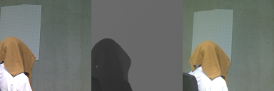
Above we have described the code to capture images from the left and right camera and 3D images from the 3D camera. We run three programs separately in three processes to overcome the problem with badly synchronized cameras. Also we have shown the code to trigger (producer) the capturing of all images by issuing a command via memory map. In Picture 3 you see an example of captured images of the left camera, 3D camera, and right camera.
Note that the left image and the right image are shifted. This is due to the fact that the CSI cameras are mounted with 8cm distance from each other. The grayscale image in the middle of Picture 3 is the 3D image. Pixels close to the camera are displayed dark, and pixels further away (in this case wall) are lighter.
We took about 3000 images from the different scenarios, mostly from persons. Unfortunately this took some time, because the 3D camera showed a delay of about half a second. So we have to wait until person is frozen before capturing three images at the same time. All images were saved into three different directories with variables dataright, dataleft and data3d.
The program below loads in the names of images into the string lists data3dlist, dataleftlist and datarightlist. All three string lists must have exactly the same image names, because each image capturing process stores images with the same name into the “left”, “right” and “3d” directories.
trainleft = os.path.join(path, r"train\left")
trainright = os.path.join(path, r"train\right")
train3d = os.path.join(path, r"train\3d")

validleft = os.path.join(path, r"valid\left")
validright = os.path.join(path, r"valid\right")
valid3d = os.path.join(path, r"valid\3d")

testleft = os.path.join(path, r"test\left")
testright = os.path.join(path, r"test\right")
test3d = os.path.join(path, r"test\3d")

dataleftlist = os.listdir(dataleft)
datarightlist = os.listdir(dataright)
data3dlist = os.listdir(data3d)

shuffle(data3dlist)

num = 20*len(data3dlist) // 100
validlist = data3dlist[:num]
testlist = data3dlist[num:num+num//10]
trainlist =  data3dlist[num+num//10:]

for name in data3dlist:
    img = cv2.imread(os.path.join(data3d,name), cv2.IMREAD_GRAYSCALE)
    img = np.array(img, dtype=np.uint8)
    assert(img.max() < limit)
The program above shuffles the string name list in data3dlist. Around 20 percent of the image names are stored into the list validlist, two percent of the image names into the list testlist and the remaining names into the list trainlist.
After executing the code below, the images are stored into the training, validation and testing directories. The program is iterating through the lists trainlist, validlist and testlist, reads in the images, and copies them to the training directory (“left”, “right”, “3d”), validation directory (“left”, “right”, “3d”) and testing directory (“left”, “right”, “3d”).
Note after reading in the left and right images, a square section with size 360×360 is taken from the images and resized to 128×128.
for name in trainlist:
    img = cv2.imread(os.path.join(data3d,name), cv2.IMREAD_GRAYSCALE)
    img = np.array(img, dtype=np.uint8)
    img_sqr = np.zeros(dim, 'uint8')
    img_sqr = img[0:dim[0],img.shape[1] - dim[1]:img.shape[1]]
    cv2.imwrite(os.path.join(train3d,name), img_sqr)

    img0 = cv2.imread(os.path.join(dataright,name), cv2.IMREAD_COLOR)
    img0 = np.array(img0, dtype=np.uint8)
    img0 = img0[60:420,120:480,:]
    img0 = cv2.resize(img0, dim, interpolation = cv2.INTER_AREA)
    cv2.imwrite(os.path.join(trainright,name), img0)

    img1 = cv2.imread(os.path.join(dataleft,name), cv2.IMREAD_COLOR)
    img1 = np.array(img1, dtype=np.uint8)
    img1 = img1[60:420,120:480,:]
    img1 = cv2.resize(img1, dim, interpolation = cv2.INTER_AREA)
    cv2.imwrite(os.path.join(trainleft,name), img1)

for name in validlist:
    img = cv2.imread(os.path.join(data3d,name), cv2.IMREAD_GRAYSCALE)
    img = np.array(img, dtype=np.uint8)
    img_sqr = np.zeros(dim, 'uint8')
    img_sqr = img[0:dim[0],img.shape[1] - dim[1]:img.shape[1]]
    cv2.imwrite(os.path.join(valid3d,name), img_sqr)

    img0 = cv2.imread(os.path.join(dataright,name), cv2.IMREAD_COLOR)
    img0 = np.array(img0, dtype=np.uint8)
    img0 = img0[60:420,120:480,:]
    img0 = cv2.resize(img0, dim, interpolation = cv2.INTER_AREA)
    cv2.imwrite(os.path.join(validright,name), img0)

    img1 = cv2.imread(os.path.join(dataleft,name), cv2.IMREAD_COLOR)
    img1 = np.array(img1, dtype=np.uint8)
    img1 = img1[60:420,120:480,:]
    img1 = cv2.resize(img1, dim, interpolation = cv2.INTER_AREA)
    cv2.imwrite(os.path.join(validleft,name), img1)

for name in testlist:
    img = cv2.imread(os.path.join(data3d,name), cv2.IMREAD_GRAYSCALE)
    img = np.array(img, dtype=np.uint8)
    img_sqr = np.zeros(dim, 'uint8')
    img_sqr = img[0:dim[0],img.shape[1] - dim[1]:img.shape[1]]
    cv2.imwrite(os.path.join(test3d,name), img_sqr)

    img0 = cv2.imread(os.path.join(dataright,name), cv2.IMREAD_COLOR)
    img0 = np.array(img0, dtype=np.uint8)
    img0 = img0[60:420,120:480,:]
    img0 = cv2.resize(img0, dim, interpolation = cv2.INTER_AREA)
    cv2.imwrite(os.path.join(testright,name), img0)

    img1 = cv2.imread(os.path.join(dataleft,name), cv2.IMREAD_COLOR)
    img1 = np.array(img1, dtype=np.uint8)
    img1 = img1[60:420,120:480,:]
    img1 = cv2.resize(img1, dim, interpolation = cv2.INTER_AREA)
    cv2.imwrite(os.path.join(testleft,name), img1)
The neural network
We decided to use the UNet neural network to predict 3D images from the left and right images. We have already good experience with UNets from past projects. The UNet was already explained in past posts and can be found here. Originally the code below was written by Tobias Sterbak and can be found here. We will not explain it in detail anymore, besides one thing, which we have modified. The last layer of the UNet is a convolutional layer, which is assigned to the variable c10. The depth of the layer is 16. The UNet model uses a container with 16 stacked images with size 128×128 each. We have described already above, that the depth images created by the 3D camera have a range of pixel values between 0 and 127. If we would use this range, we would need a UNet model, which generates 128×128 images with 128 stacks (each stack indicates a distance from the camera). These are huge data containers and would exceed the graphic card capacity during training. For this reason we limit the image size for predicted images to 128x128x16.
def conv2d_block(input_tensor, n_filters, kernel_size=3, batchnorm=True):
    x = Conv2D(filters=n_filters, kernel_size=(kernel_size, kernel_size), kernel_initializer="he_normal",
               padding="same")(input_tensor)
    if batchnorm:
        x = BatchNormalization()(x)
    x = Activation("relu")(x)
    x = Conv2D(filters=n_filters, kernel_size=(kernel_size, kernel_size), kernel_initializer="he_normal",
               padding="same")(x)
    if batchnorm:
        x = BatchNormalization()(x)
    x = Activation("relu")(x)
    return x

def get_unet(input_img, n_filters=16, dropout=0.5, batchnorm=True):
    c1 = conv2d_block(input_img, n_filters=n_filters*1, kernel_size=3, batchnorm=batchnorm)
    p1 = MaxPooling2D((2, 2)) (c1)
    p1 = Dropout(dropout*0.5)(p1)

    c2 = conv2d_block(p1, n_filters=n_filters*2, kernel_size=3, batchnorm=batchnorm)
    p2 = MaxPooling2D((2, 2)) (c2)
    p2 = Dropout(dropout)(p2)

    c3 = conv2d_block(p2, n_filters=n_filters*4, kernel_size=3, batchnorm=batchnorm)
    p3 = MaxPooling2D((2, 2)) (c3)
    p3 = Dropout(dropout)(p3)

    c4 = conv2d_block(p3, n_filters=n_filters*8, kernel_size=3, batchnorm=batchnorm)
    p4 = MaxPooling2D(pool_size=(2, 2)) (c4)
    p4 = Dropout(dropout)(p4)

    c5 = conv2d_block(p4, n_filters=n_filters*16, kernel_size=3, batchnorm=batchnorm)

    u6 = Conv2DTranspose(n_filters*8, (3, 3), strides=(2, 2), padding='same') (c5)
    u6 = concatenate([u6, c4])
    u6 = Dropout(dropout)(u6)
    c6 = conv2d_block(u6, n_filters=n_filters*8, kernel_size=3, batchnorm=batchnorm)

    u7 = Conv2DTranspose(n_filters*4, (3, 3), strides=(2, 2), padding='same') (c6)
    u7 = concatenate([u7, c3])
    u7 = Dropout(dropout)(u7)
    c7 = conv2d_block(u7, n_filters=n_filters*4, kernel_size=3, batchnorm=batchnorm)

    u8 = Conv2DTranspose(n_filters*2, (3, 3), strides=(2, 2), padding='same') (c7)
    u8 = concatenate([u8, c2])
    u8 = Dropout(dropout)(u8)
    c8 = conv2d_block(u8, n_filters=n_filters*2, kernel_size=3, batchnorm=batchnorm)

    u9 = Conv2DTranspose(n_filters*1, (3, 3), strides=(2, 2), padding='same') (c8)
    u9 = concatenate([u9, c1], axis=3)
    u9 = Dropout(dropout)(u9)
    c9 = conv2d_block(u9, n_filters=n_filters*1, kernel_size=3, batchnorm=batchnorm)

    c10 = Conv2D(depth, (1, 1), activation="softmax") (c9)

    model = Model(inputs=[input_img], outputs=[c10])
    return model
If we divide all 3D camera images by 8, we limit the pixel value range from 0 to 15. For training however, we need to convert the 3D images with 128×128 shape (and a 0 to 15 pixel range) to images with a 128x128x16 shape. The set of a pixel values will then only be zero or one. The image converting function is shown below. A while loop iterates through all pixel values (from 0 to 15) and moves zeros or ones into the corresponding image stack of the return image.
def makecolormask(mask):

    ret_mask = np.zeros((mask.shape[0], mask.shape[1], depth), 'uint8')

    for c in range(depth):
        ret_mask[:, :, c] = (mask == c).astype(int)

    return ret_mask
Training
We use generators to load in batches of images during training time. Due to the size of the training images (especially the 3D image), we easily exceed the graphic card and computers memory capacity, so the training images are loaded in batches from disk during the training process. The function generatebatchdata has already been described here. Note that this function is dividing 3D image pixel values by 8 to reduce the pixel value range to 0 to 15. You also find the function makecolormask used in generatebatchdata. To have only one input image container, the left and right image are stacked together to a single 128x128x6 image. More about it below.
def generatebatchdata(batchsize, inputpath):

    imagenames = os.listdir(os.path.join(path, inputpath, "3d"))

    shuffle(imagenames)

    while True:
        batchstart = 0
        batchend = batchsize

        while batchstart < len(imagenames):

            imagelist = []
            masklist = []

            limit = min(batchend, len(imagenames))

            for i in range(batchstart, limit):
                if imagenames[i].endswith(".png"):
                    img0 = cv2.imread(os.path.join(path, inputpath, "right",imagenames[i]),cv2.IMREAD_COLOR )
                    img1 = cv2.imread(os.path.join(path, inputpath, "left",imagenames[i]),cv2.IMREAD_COLOR )

                    img = np.zeros((dim[0], dim[1], img0.shape[2]+img1.shape[2]), 'uint8')
                    img[:,:,0:img0.shape[2]] = img0[:,:,:]
                    img[:,:,img0.shape[2]:img0.shape[2]+img1.shape[2]] = img1[:,:,:]

                    imagelist.append(img)

                    mask = cv2.imread(os.path.join(path, inputpath, "3d",imagenames[i]),cv2.IMREAD_UNCHANGED )
                    mask //= 8
                    masklist.append(makecolormask(mask))


            train_data = np.array(imagelist, dtype=np.float32)
            train_mask= np.array(masklist, dtype=np.float32)

            train_data -= train_data.mean()
            train_data /= train_data.std()

            yield (train_data,train_mask)

            batchstart += batchsize
            batchend += batchsize
During training, the model needs to be fed with input images, which are left and right images captured by the CSI cameras. Left and right images have both the size 128x128x3 since they are RGB images. In order to feed both images in one shot into the model, we stack left and right images to 128x128x6 images. The first line of the code shows, that the model is configured with input size 128x128x6. The remaining code below, such as the callbacks, has already been described in previous posts.
input_img = Input((dim[0], dim[1], 6), name='img')
model = get_unet(input_img, n_filters=depth, dropout=0.0, batchnorm=True)
model.compile(optimizer=Adam(), loss="categorical_crossentropy", metrics=["accuracy"])

callbacks = [
    EarlyStopping(patience=10, verbose=1),
    ReduceLROnPlateau(factor=0.1, patience=3, min_lr=0.00001, verbose=1),
    ModelCheckpoint(os.path.join(path, dirmodels,"model-chkpt.h5"), verbose=1, save_best_only=True, save_weights_only=True)
]
The program below instantiates two generators generator_train and generator_valid. We use the batch size of 20. The training is started with the fit_generator command (in keras, this function is deprecated by now, so you can just replace with the fit command).
batchsize = 20

generator_train = generatebatchdata(batchsize, "train")
generator_valid = generatebatchdata(batchsize, "valid")

model.fit_generator(generator_train,trainsize//batchsize, epochs=20, callbacks=callbacks, validation_data=generator_valid, validation_steps=validsize//batchsize)
On jupyter notebook we are able to execute the above portion of code several times in a row, so we ran the training with 80 epochs. At the end we had a validation accuracy of 82%. Considering that we have just 3000 training images (minus 20 percent validation images), the result might be just fine. We stopped the training after 80 epochs, because we were not able to see any improvement.
Testing on a Jetson Nano
We ran the training on a NVIDIA 2070 graphics card and saved the weights to a file with name modelweightname. For testing, we use the Jetson Nano on the same experimental setup, which has been described above. Below you see how the model can be loaded from a json file and how the weights can be loaded into the model.
json_file = open(os.path.join(path, models,modeljsonname), 'r')
loaded_model_json = json_file.read()
json_file.close()
model = model_from_json(loaded_model_json)
model.load_weights(os.path.join(path, models,modelweightname))
Essentially we use similar code as above to capture left and right images from the CSI cameras by using the VideoCapture class. The code below instantiates the objects outle, outri and out3d from the VideoWriter class to write videos from the captured images and from the predicted 3D image.
Within the while loop the program captures images from the left and right CSI cameras, extracts a square section and then resizes them. Finally they are stacked together, standardized and pushed into the trained model for prediction. The output of a prediction is a 128x128x16 image which is converted to a 3D image by using the numpy reshape/argmax functions. The left, right and 3D image are then written into the video streams.
cap0 = cv2.VideoCapture(gstreamer(sensor_id=0), cv2.CAP_GSTREAMER)
cap1 = cv2.VideoCapture(gstreamer(sensor_id=1), cv2.CAP_GSTREAMER)

out3d = cv2.VideoWriter(os.path.join(path,"videos",'video3d.mp4'),cv2.VideoWriter_fourcc(*'MP4V'),10, dim)
outle = cv2.VideoWriter(os.path.join(path,"videos",'videole.mp4'),cv2.VideoWriter_fourcc(*'MP4V'), 10, dim)
outri = cv2.VideoWriter(os.path.join(path,"videos",'videori.mp4'),cv2.VideoWriter_fourcc(*'MP4V'), 10, dim)

img0 = None
img1 = None
predictions_test = None

while(True):
    ret0, frame0 = cap0.read()
    ret1, frame1 = cap1.read()

    if ret0 == True and ret1 == True:


        cv2.imshow('left', frame0)
        cv2.imshow('right', frame1)

        img0 = np.array(frame1, dtype=np.uint8)
        img0 = img0[60:420,120:480,:]
        img0 = cv2.resize(img0, dim, interpolation = cv2.INTER_AREA)

        outri.write(img0)

        img1 = np.array(frame0, dtype=np.uint8)
        img1 = img1[60:420,120:480,:]
        img1 = cv2.resize(img1, dim, interpolation = cv2.INTER_AREA)

        outle.write(img1)

        img = np.zeros((dim[0], dim[1], img0.shape[2]+img1.shape[2]), 'uint8')
        img[:,:,0:img0.shape[2]] = img0[:,:,:]
        img[:,:,img0.shape[2]:img0.shape[2]+img1.shape[2]] = img1[:,:,:]

        imagetestlist = []
        imagetestlist.append(img)
        test_data = np.array(imagetestlist, dtype=np.float32)
        test_data -= test_data.mean()
        test_data /= test_data.std()

        prediction = model.predict(test_data, batch_size=1, verbose=0)[0]

        mymask = prediction.reshape((dim[0], dim[1], depth)).argmax(axis=2)

        mymask *= 8
        mymask =  np.array(mymask, dtype=np.uint8)

        out3d.write(cv2.cvtColor(mymask,cv2.COLOR_GRAY2RGB))

        mask = np.zeros(((2*dim[0], 2*dim[1])), 'uint8')
        mask = cv2.resize(mymask, (2*dim[0], 2*dim[1]), interpolation = cv2.INTER_AREA)

        cv2.imshow('3d',mask)

        if cv2.waitKey(1) & 0xFF == ord('q'):
            break
    else:
        print("camera not workin")
        break

cap0.release()
cap1.release()
cv2.destroyAllWindows()
out3d.release()
outle.release()
outri.release()
Above we described a problem with unsynchronized capturing of images with the left and right CSI cameras. The code above does not show this problem we had before. We assume it is due to the very slow inference computation time for the 3D image prediction. Both cameras seem to catch up, because the real bottleneck here is the 3D image prediction.
Results
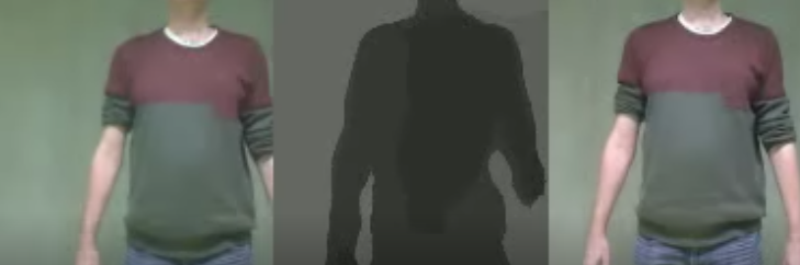
Picture 4 shows images from the left, right and 3D camera videos. Note that the left and right images are shifted, since both cameras are mounted 8cm apart. In the middle of Picture 4 you see the predicted 3D image. The hand on the right side of the 3D image seems to be cut off. This is probably due to the left camera, which did not capture the complete hand.
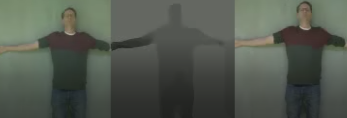
In Picture 5 you see a person leaning against the wall. The wall pixels should have the values around 127. In the text above we described, that we furthest distance we work with is 2m, which is represented by the pixel value 127. In the middle of Picture 5 you see that the person is displayed slightly darker than the wall. This is expected. But the hand on the left side is actually to dark.
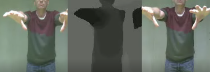
In Picture 6 you see a person stretching out this hands towards the cameras. In the middle of Picture 6, the hands are displayed with dark pixels, while the body is displayed with lighter pixels. This is expected. On the right side in the 3D image, there is a section which has just been left out and shows wall distance pixels.
Conclusion and Outlook
The pictures in the result section show how 3D predictions are possible with a trained model. The results you find here have a qualitative nature; so we can recognize, that a person is close or far away from the camera. Until now, we have not made any quantitative tests, by determining a pixel value and relate it to a real distance of an object from the camera’s lens.
The 3D images are predicted by a trained model. We mentioned above, that we only used 3000 images and had a validation accuracy of 82%. The validation accuracy probably can be improved, if we use many more images for training.
The imperfect accuracy can be seen in the pictures of the result section. In one case, a hand was missing. In another case, a hand was displayed as if it is close to the camera, though it was leaning against the wall. We assume that these imperfections can be improved with more training data.
To our surprise the performance of the Jetson Nano computer is not too good with the model we use. We really did ensure that the NVIDIA chip was used during prediction. Despite the graphic card chip, the inference time to predict 3D image is too high. The display of the predicted 3D images is not in real time. Hence, you always see a delay of several seconds. For further improvement, we might need to take out a more layers from the model to reduce the calculations.
Another topic which should be investigated in more detail is, if a convolutional neural network is really suited for this kind of problem. We need to show, if the shift of the images between the left and right cameras do come in effect at all. Convolutional network only consider direct neighbor pixels (depending on its kernel size, which is often just 3×3), and not pixels which are further apart like in our case with the left and right picture. More investigation should be made to take this shift more into account, maybe with fully connected layers or with larger kernels.
Acknowledgement
Special thanks to the University of Applied Science Albstadt-Sigmaringen for providing the infrastructure and the appliances to enable this research.